What I learned setting up Reprap Discount Smart Controller
ReprapDiscount Full Graphic Smart Controller install on youtube
Discount Full Graphic Smart Controller Marlin variables
I've been working with Marlin 1.1.8 configuration starting from scratch and it took surprising amount of effort to find the correct variables to enable the screen.
This particular screen is used on Creality Ender 3, so it might have been easier to look at their default marlin config.
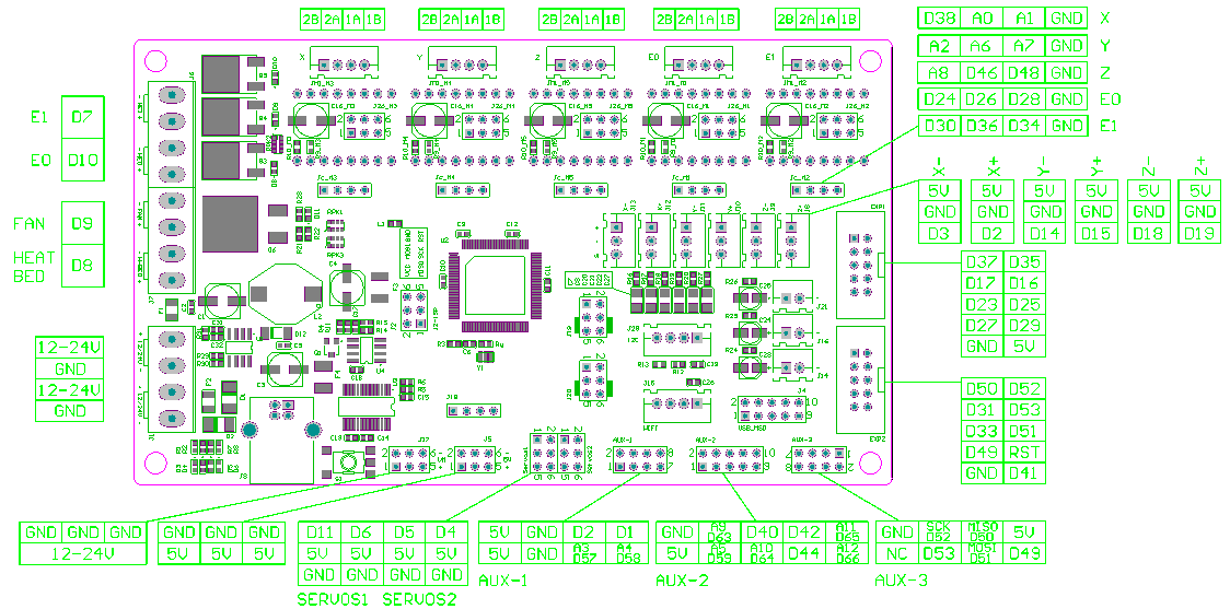
The video above goes in other details what dependencies Arduino IDE needs in order to compile screen config, but as far as Marlin setup is concerned, all it takes is defining the following two variables in configuration Configuration.h
#define REPRAP_DISCOUNT_FULL_GRAPHIC_SMART_CONTROLLER
#define SDCARD
Smart Controller box
I could not detach the plastic knob from the rotary encoder stick.
Instead of using force and possibly breaking knob, encoder, screen or all of the above; I redesigned the smart controller box to have a bigger opening for so the whole knob would fit through it.
This may not look as neat as the original design, but it works.
Design files
Original ReprapDiscount Full Graphic Smart Controller Box in OpenSCAD box
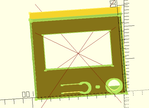
Modified ReprapDiscount Full Graphic Smart Controller Box (top part)
wildcard prefix
Reading the code for the box for the controller, * wildcard character as a prefix is used to disable the following statement, or as the documentation refers to it, entire subtree.
In the snippet below only lcdbox_top() is executed.
lcdbox_top();
*lcdbox_bottom();
*lcdbox_knob();
*translate([0,(nut_m3[0]+stable_wall*2)/2+1,0]) lcdbox_mount();
*translate([0,-extrusion_width/2-1,0]) lcdbox_mount_bottom();
30-degree screen mount
I wanted to have a single printer part mount for the screen at 30 degrees that would fit more-or-less snug into a 2020 slot using the the hardware I have. This design needs an extra 10mm M5 bolt and an M5 T-nut.
I've been using the screen in this configuration for a few months and I haven't felt any need to adjust its angle. I believe the design serves its purpose.
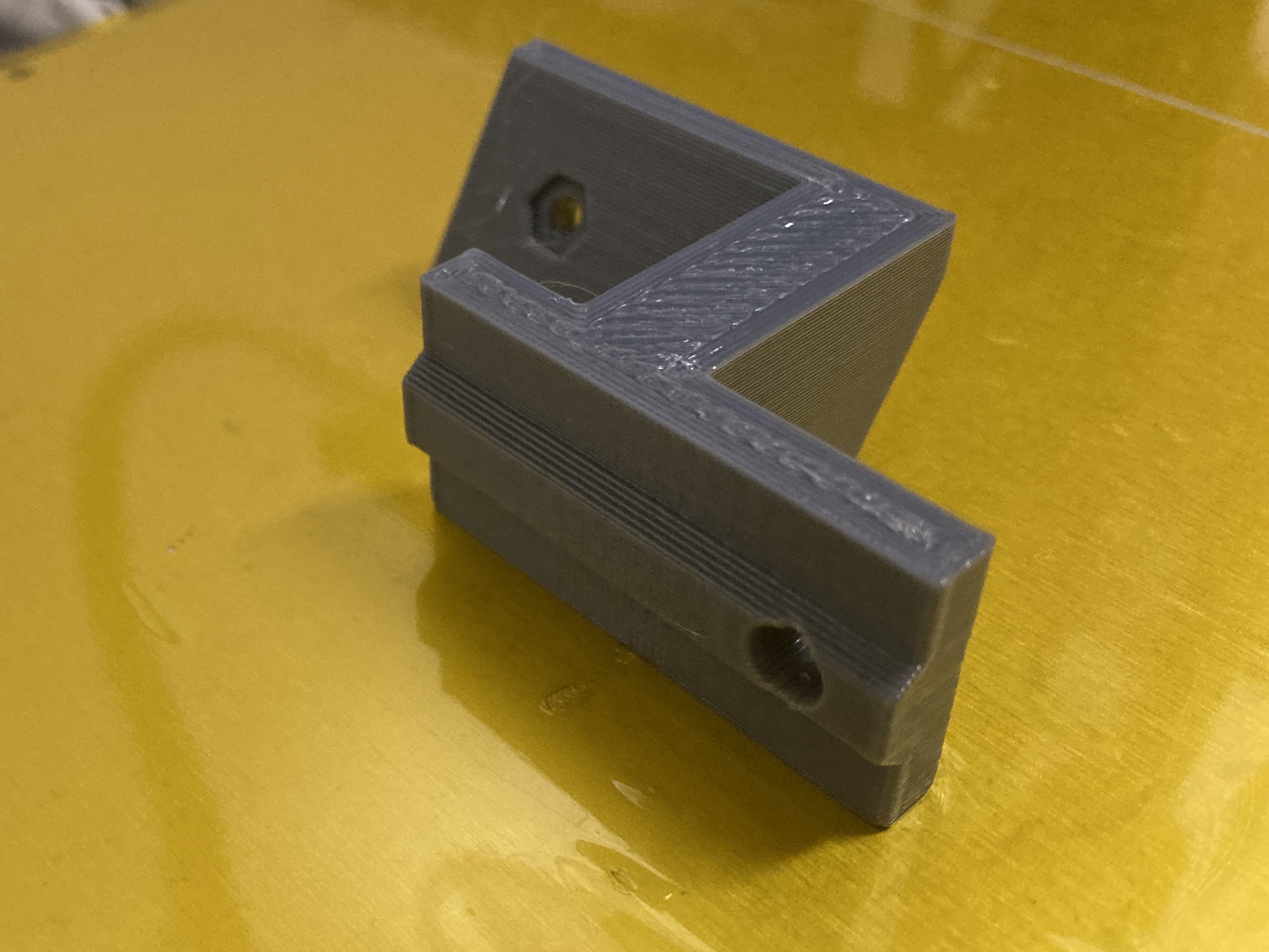
The part above was printed with 0.5mm nozzle at 0.3mm Z height using PETG.
Design files
Polygon & linear extrude
To go beyond just using primitive solids in openscad, polygon and linear_extrude come really handy.
In the case of screen leg holder, I used this to create a protrusion that goes into 2020 Alu profile channel. First create a shape that fits into profile gap, I measured some of the Bear Upgrade printed parts, with the height of 2mm base of the shape 8mm and the top of 4mm.
polygon(points=[[0,0], [2,1.5], [2, 6.5], [0, 8]]);
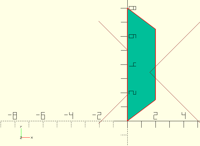
Then extruding that shape in Z direction usingl linear_extrude will produce a 40mm-long section that will fit into the aluminium extrusion.
linear_extrude(40)
    polygon(points=[[0,0], [2,1.5], [2, 6.5], [0, 8]]);
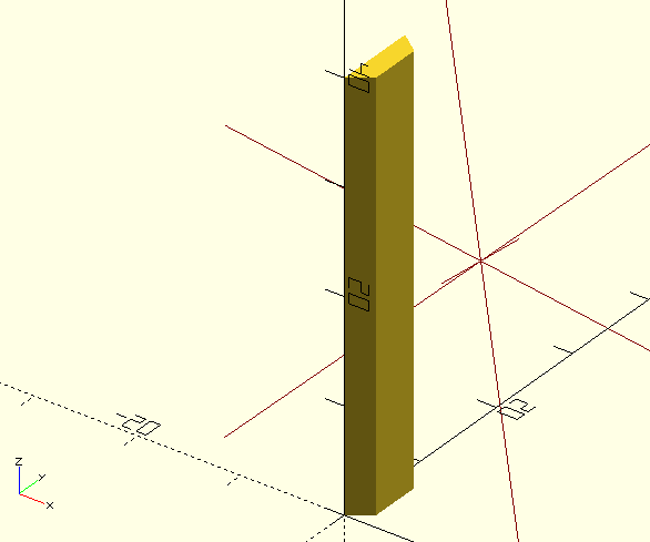
The resulting part fits in ALU slot profile with some play, before M5 bolt is fully tightened. I need to adjust the tolerances to make it fit snugly when tightening the bolt, but what I have is definitely usable.